|
|
|
Who's Online
There currently are 6043 guests online. |
|
Categories
|
|
Information
|
|
Featured Product
|
|
|
 |
|
|
There are currently no product reviews.
 ;
perfect copy, im very satisfied, i was need the diagram over the powersupply and
the copy was very sharp
;
This is exactly the service manual I needed.
Complete with all schematics, partslists, PCB layouts and alignment instructions.
This manual covers both the T-4970 en T-488F Onkyo tuner.
 ;
IF PRINTED CIRQUIT BOARD WIRING VIEW WAS ONE TONE LIGHTER, THEN 5 STAR RANK HAS TO BE MY CHOISE.
;
Very usefull, good quality drawings !
Muito útil encontrei todas as informações necessárias.
;
Wanting to repair a neighbours tape recorder I needed the necessary information, it makes it easier. Although the service manual is described as "Language : English" To my dismay I found that it is entirely written in German, a language I do not understand. At least I now have the schematics which will help of sorts. I may not use this service again due to the laguage difficulty after all when it states English you do not expect it to be entirely in another language.
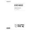
7. Wiring diagram
Wiring for Circuit Power Supply and Ballast Power Supply Boards
Wiring for Circuit Power Supply Board (1) Keep a record of the circuit power supply lot number in the 100% inspection record. (2) Connect the TSW. (3) Install the FEB3. (4) Connect the CNPOW. (5) Connect the CNTH. (6) Apply the TAP3. Wiring for Ballast Power Supply Board (1) Keep a record of the ballast power supply lot number in the 100% inspection record. (2) Cut off the PVC sheet. (3) Connect the CNPWR. (4) Install the FEB2. (5) Connect the CNBAR. (6) Install the ballast shield (in accordance with the general assembly drawing). Connect the FEB2 (ferrite core) to the CNPWR then move the CNPWR to the connector as illustrated below:
CP-S318(C3SM4) / CP-X328(C3XM4)
CN101
1pin
CN104
2-8pin J2
FEB3 9-14pin
CNPOW
J1
CN102
TSW Pass the leads through the board holder notch.
Connect the CNPWR to connector J1 then make sure that the CNPWR is completely locked.
FEB2
CNPWR
30
Sensor board Connect the CNTH to connector E950 on the sensor board. E950 Sensor board CNTH
CNBAR
Connect the FEB3 (ferrite core) to pins 2-8 of the CNPOW.
Connect the CNBAR to connector J2, while holding down the small board mounted with the J2 (to prevent stress on the small board).
Make sure that the CN102 and the CN104 have been securely connected (since they cannot be checked in subsequent processes).
Cut off the PVC sheet by bending it back and forth 2 or 3 times with your hand, while holding down the double-coated adhesive tape affixed to the igniter transformer so the tape cannot come off. Igniter transformer
Install the sensor board after completing the following steps: Make sure that connector E950 has been securely connected then apply the TAP3 (to prevent detachment).
Perforation
Cut off the sheet by bending it back and forth 2 or 3 times.
TAP3
C3SM4 / C3XM4 Chassis Wiring diagram 1
|
|
|
> |
|