|
|
|
Who's Online
There currently are 6043 guests online. |
|
Categories
|
|
Information
|
|
Featured Product
|
|
|
 |
|
|
There are currently no product reviews.
 ;
I thank Owner-Manuals.com for providing the necessary manual very quickly, and it was very helpful in repairing my personal Audio System and I once again thank them for the wonderful customer's service satisfaction.
Thanks.
;
Everything fine: quick service, no glitch and above all a very good quality of the Pdf file. Thank you!
;
The manual was complete, parts list, adjustment procedures, etc. No worries
 ;
Very usefully, I could find the trouble clearly with that manual.
;
Bon produit. Permet de corriger les couleurs et de redonnez un petit coup de jeune à vos vieilles vidéos. On regrettera juste le manque d'une prise s-vidéo.
CHAPTER 2
1 . Procedure
Component to be removed
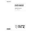
DISASSEMBLY
The numbers in the followinng tables correspond to those in Fig. 1-1. Remove each component shown in the following tables according to the order of the numbers. Item Front case (1) Top case (1) (2) Rear panel (1) (2) (3) (4) (5) Rear PWR EXT & PC f r a m e c i r c u i t circuit a ' s s y board board (1) (1) (1) (2) (2) (2) (3) (3) (3) (4) (4) (4) (5) (5) (5) (6) (6) (6) (7) (7) (8) (8) (9) (10) (11) (12) (13) (14) (15) How to remove
(1) Remove 1 screw holding the front case. (2) Remove 4 screws holding the top case. (3) Remove 2 screws holding the rear panel. (4) Remove 2 screws holding the bottom case. (5) Release 2 tabs. (6) Remove 2 screws. (7) Disconnect 2 connectors on the BNC circuit board. (8) Disconnect 1 connector on the AC circuit board. (9) Remove 2 screws holding the PWR frame. (10) Disconnect 1 connector on the PWR circuit board. (11) Remove 3 screws holding the PWR circuit board. (12) Disconnect 3 connectors on the PC circuit board. (13) Remove 2 screws holding the bottom case. (14) Remove 1 screw and remove the EXT circuit board in the direction of the arrow. (15) Remove the PC circuit board in the direction of the arrow.
Removal Procedure and Number of Component to be removed
Lens CCD AC BNC SW Bottm I t e m b l o c k sensor & c i r c u i tc i r c u i tc i r c u i t c a s e S circuit b o a r d b o a r d b o a r d (1) board & AC (1) (2) (1) terminal ( 1 ) (1) (2) (3) (2) (1) (2) (2) (3) (4) (3) (2) (3) (3) (4) (5) (4) (3) (4) (4) (5) (6) (5) (4) (5) (5) (6) (6) (5) (6) (6) (7) (6) (7) (7) (8) (7) (8) (8) (12) (8) (13) (12) (14) (13) (14) (15) (15) (16) (17) (16) (18) (17) (18) (19) (20) (21) (22)
How
to
remove
(23)
(23) (24) (25)
(26)
(1) Remove 1 screw holding the front case. (2) Remove 4 screws holding the top case. (3) Remove 2 screws holding the rear panel. (4) Remove 2 screws holding the bottom case. (5) Release 2 tabs. (6) Remove 2 screws. (7) Disconnect 2 connectors on the BNC circuit board. (8) Disconnect 1 connector on the AC circuit board. Note: Steps (9) to (11) are not necessary. (12) Disconnect 3 connectors on the PC circuit board. (13) Remove 2 screws holding the bottom case. (14) Remove 1 screw and remove the EXT circuit board in the direction of the arrow. (15) Remove the PC circuit board in the direction of the arrow. (16) Disconnect 1 connector on the S circuit board. (17) Remove 2 screws holding the lens block. (*1) (18) Remove 4 screws holding the lens block. (19) Unsolder 14 points (CCD sensor) on the S circuit board. (20) Remove 2 screws holding the S circuit board. (21) Remove 2 screws holding the AC terminal. (22) Unsolder 2 points on the AC circuit board. (23) Unsolder 2 points on the BNC circuit board. (24) Unsolder 9 points on the SW circuit board. (25) Remove 1 screw holding the SW circuit board. (26) Remove 2 screws holding the bottom case.
*1: When the lens block is removed, the crystal filter and rubber are also removed. Be careful not to damege and lose them.
2-1
|
|
|
> |
|